A robot is more than one program. One tool draws it, another computes where its hand is, another plans a motion without hitting its own base, another simulates its weight. Each of them needs the same facts: how many joints, how long each link is, where each axis points, how far each joint may turn.
If every tool keeps its own copy of these facts, they drift apart. A link is lengthened in the planner and not in the viewer, and the robot on the screen no longer matches the robot that plans.
ROS avoids this with a single description of the robot, the URDF (Unified Robot Description Format), an XML file that describes the robot model [1]. This post follows that file: what it stores, what it does not, and who reads it in ROS 2, from robot_state_publisher to MoveIt.
robot_description parameter, and every other tool derives what it needs from it: the TF frames, the collision checks, the simulated masses. A wrong value in the URDF is wrong everywhere at once.What a URDF stores
A URDF describes a robot as a set of links (rigid bodies) connected by joints. Each joint has a parent link and a child link, so the robot is a tree with one root link [1].
Links: what a body looks like and weighs
A link can carry three descriptions of the same body [1], [3]:
visual: the shape to draw, with its material and colour;collision: the shape used to detect contacts. It is often simpler than the visual one;inertial: the mass, the centre of mass and the inertia matrix.
The three are separate on purpose. A link drawn with a detailed 3D mesh of thousands of triangles can collide as a plain box or cylinder: two cylinders are checked against each other with a few formulas, while two meshes mean comparing triangles with triangles. Collision detection between two meshes is a lot more complex than between two simple geometries [3], and the number of triangles drives the time of each check [8]. In the example below, upper_arm is drawn with a mesh and collides as a box.
The inertial element is needed for every link that is simulated [3].
Joints: how two bodies move relative to each other
A joint connects a parent link to a child link, and it answers three questions: where it sits (origin), which way it moves (axis) and how far (limit) [1], [2].
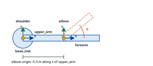
Each link has its own frame: a point and three axes, x, y and z. The origin of a joint is defined in the reference frame of the parent link, and the frame of the child link sits at that point [1]. Positions are in metres [1] and the limits of a revolute joint are in radians [2]. Fig. 1 shows it on the arm of the example that follows.
The type of the joint tells how the child moves relative to the parent. It is one of six [1], [2]:
| Type | Motion |
|---|---|
revolute | hinge: rotation around the axis, within a lower and an upper limit |
continuous | hinge without limits: any angle, from minus infinity to plus infinity |
prismatic | slide along the axis, within a lower and an upper limit (in metres) |
fixed | no motion |
floating | unconstrained, free to move in any of the three dimensions |
planar | motion in a plane, in two dimensions |
The limit element holds the lower and upper positions and the maximum velocity and effort [2].
A minimal example
Here is a two-joint arm, written for this post (the values are illustrative, it is not a real robot):
<robot name="two_dof_arm">
  <link name="base_link">
    <visual><geometry><cylinder length="0.1" radius="0.08"/></geometry></visual>
    <collision><geometry><cylinder length="0.1" radius="0.08"/></geometry></collision>
    <inertial>
      <mass value="2.0"/>
      <inertia ixx="0.01" ixy="0" ixz="0" iyy="0.01" iyz="0" izz="0.01"/>
    </inertial>
  </link>

  <joint name="shoulder" type="revolute">
    <parent link="base_link"/>
    <child link="upper_arm"/>
    <origin xyz="0 0 0.05" rpy="0 0 0"/>   <!-- metres, radians -->
    <axis xyz="0 0 1"/>                      <!-- rotates around z -->
    <limit lower="-2.0" upper="2.0" velocity="1.0" effort="30"/>
  </joint>

  <link name="upper_arm">
    <visual>      <!-- the detailed shape, to draw -->
      <origin xyz="0.15 0 0"/>
      <geometry><mesh filename="package://two_dof_arm/meshes/upper_arm.stl"/></geometry>
    </visual>
    <collision>   <!-- a simple box, to check contacts -->
      <origin xyz="0.15 0 0"/>
      <geometry><box size="0.3 0.05 0.05"/></geometry>
    </collision>
  </link>

  <joint name="elbow" type="revolute">
    <parent link="upper_arm"/>
    <child link="forearm"/>
    <origin xyz="0.3 0 0" rpy="0 0 0"/>
    <axis xyz="0 0 1"/>
    <limit lower="-2.5" upper="2.5" velocity="1.0" effort="20"/>
  </joint>

  <link name="forearm">
    <visual><origin xyz="0.125 0 0"/><geometry><box size="0.25 0.04 0.04"/></geometry></visual>
  </link>
</robot>
Read it as a chain: base_link → shoulder → upper_arm → elbow → forearm. The origin of elbow places it 0.3 m along the x axis of upper_arm, which is its tip.
Two kinds of origin appear in this example, and they do not mean the same thing:
- the
originof a joint places the frame of the child link in the frame of the parent link. Forelbow, the frame offorearmis 0.3 m along the x axis ofupper_arm[1]; - the
originof a visual or a collision places the shape in the frame of its own link. A shape is centred on that frame by default [1], so inupper_armthe offset of 0.15 m moves the box, which is 0.3 m long, to start at the joint instead of being centred on it.
What a URDF does not store
The URDF format describes bodies and joints. Two things that a robot needs are not in the base format:
- Motion planning information. Which joints form the arm, which pairs of links may touch, what the home pose is: this is the job of a second file, the SRDF, described below [8].
- The state of the robot. The URDF gives the structure, not the current angles. The joint positions are published as
JointStatemessages: in the ROS 2 tutorial, the sliders of a GUI do it [2].
In practice the file does carry more than the base format, because other tools add their own tags to it. Gazebo-specific tags exist [3], ros2_control reads a <ros2_control> block placed in the URDF, where the hardware plugin is declared [10], and the MoveIt Setup Assistant has a step that modifies the URDF for ros2_control [9]. The URDF is therefore the place where the tools meet, but each one reads only its own part.
Nobody writes it by hand: xacro
A URDF repeats itself: two similar links, the same numbers in the visual and the collision shapes, the same colour on every part. xacro is an XML macro language that removes this repetition with constants, simple maths and macros, and the xacro program expands them into a plain URDF [4]:
xacro model.xacro > model.urdf
Here are the two arm links of the example above, written in xacro. The file starts with the xacro namespace, which is required for the file to parse [4]:
<robot xmlns:xacro="http://www.ros.org/wiki/xacro" name="two_dof_arm">

  <!-- constants: defined once, used with ${...} -->
  <xacro:property name="arm_width" value="0.05"/>
  <xacro:property name="arm_rgba"  value="0.2 0.4 0.8 1"/>

  <!-- a macro: one definition for both links -->
  <xacro:macro name="arm_link" params="name length">
    <link name="${name}">
      <visual>
        <origin xyz="${length/2} 0 0"/>   <!-- simple maths -->
        <geometry><box size="${length} ${arm_width} ${arm_width}"/></geometry>
        <material name="${name}_blue"><color rgba="${arm_rgba}"/></material>
      </visual>
      <collision>
        <origin xyz="${length/2} 0 0"/>
        <geometry><box size="${length} ${arm_width} ${arm_width}"/></geometry>
      </collision>
    </link>
  </xacro:macro>

  <xacro:arm_link name="upper_arm" length="0.3"/>
  <xacro:arm_link name="forearm"   length="0.25"/>

</robot>
The size and the colour are written once: changing arm_width or arm_rgba changes the visual and the collision shapes of both links. The offset ${length/2} is computed from the length, so the origin follows if a link is made longer. After expansion, the call <xacro:arm_link name="upper_arm" length="0.3"/> gives, formatting aside, this plain URDF:
<link name="upper_arm">
  <visual>
    <origin xyz="0.15 0 0"/>
    <geometry><box size="0.3 0.05 0.05"/></geometry>
    <material name="upper_arm_blue"><color rgba="0.2 0.4 0.8 1"/></material>
  </visual>
  <collision>
    <origin xyz="0.15 0 0"/>
    <geometry><box size="0.3 0.05 0.05"/></geometry>
  </collision>
</link>
A launch file can run the expansion at startup, so the .urdf is never edited [4]. A URDF can also be generated from a CAD model: MoveIt’s documentation points to a plugin for SolidWorks [8].
Who reads it in ROS 2
source with macros"/] --> X[/"xacro
expands the macros"\] X --> P{{"robot_description
parameter =
the URDF text"}} P --> RSP["robot_state_publisher"] P --> MV["MoveIt"] S[/"robot.srdf"/] --> MV PUB["node publishing the current
joint states (e.g. ros2_control)"] --> JS(["/joint_states"]) JS --> RSP JS --> MV RSP --> TF(["/tf and /tf_static"]) TF --> RV[["RViz"]] classDef file fill:#F1EEE4,stroke:#8a8467,color:#3b3a2f classDef tool fill:#FBE3D2,stroke:#c2591a,color:#6b2f0a classDef param fill:#DDF1E8,stroke:#1f7a5a,color:#0f4a36 classDef topic fill:#DBE8F8,stroke:#024a98,color:#0B3A78 classDef node fill:#FFEFC2,stroke:#E5D28A,color:#6B4A00 classDef app fill:#EBDDF5,stroke:#6b3fa0,color:#3d1f63 class F,S file class X tool class P param class TF,JS topic class RSP,MV,PUB node class RV app
Fig. 2 shows the path from the source file to the tools. Three readers matter most in daily work.
robot_state_publisher takes the URDF, supplied through the robot_description parameter, and the joint_states topic, and publishes the resulting poses to tf2 [6]. The next section details it.
What does this parameter contain? The whole text of the URDF: it is a string of XML, not the path of a file [6]. A launch file fills it by running xacro on the file and passing the output as the value of robot_description [4], [11]. Every node that needs the model reads this text and parses it.
MoveIt uses the meshes of the URDF for collision checking, and it compares the joint limits of the URDF with the soft limits of an optional safety_controller, keeping the more conservative ones [8]. MoveIt also needs the /joint_states topic: without it, its documentation says, it has no feedback from the joints [14]. The URDF only describes the physical joints, so MoveIt adds an SRDF file for the rest (see below).
Simulation and control need the collision and inertial elements to simulate a link [3], and ros2_control finds its hardware declaration in the URDF [10]. It also closes the loop: its joint_state_broadcaster reads the state interfaces of the hardware and reports them on /joint_states [13].
From a joint angle to a TF frame
robot_state_publisher is the link between the static description and a moving robot. Its README describes the sequence [6].
robot_description parameter, and must be set at startup. The node also republishes it on a robot_description topic, with a transient local QoS, so that other tools can read the current model. A mode exists where the node reads the description from that topic instead.fixed cannot move, so their transforms go to the transient local /tf_static topic one time, at startup. A subscriber that starts later still receives them.joint_states (sensor_msgs/msg/JointState). The URDF gives the structure, but not the angles: someone else has to publish them. On a robot driven by ros2_control, its joint_state_broadcaster does it [13]. In the ROS 2 tutorials, a small node [5] or the sliders of a GUI [2] publish the JointState messages instead. Without this topic, only the fixed frames exist./tf. The maximum rate for these transforms is the publish_frequency parameter, 20 Hz by default.The result is a TF tree whose frame names are the link names of the URDF. This is why a link named forearm in the file is the frame forearm for every node that asks tf2 where something is. The frame conventions, such as base_link being rigidly attached to the mobile base, are defined in REP 105 [7].
Seeing it in RViz
The whole chain of Fig. 2 can be run without writing any code. The urdf_launch package has two launch files for it. description.launch.py runs xacro on the file and starts robot_state_publisher with the result as robot_description [11]. display.launch.py does the same and adds RViz with a preconfigured setup, and a joint state publisher with an optional GUI [12]. The ROS 2 URDF tutorials use the same idea with the display.launch.py of urdf_tutorial, which loads the model as a parameter of robot_state_publisher, publishes joint states and transforms, and starts RViz [1]:
ros2 launch urdf_launch display.launch.py \
  urdf_package:=two_dof_arm urdf_package_path:=urdf/two_dof_arm.urdf
two_dof_arm is a ROS 2 package of your own that contains the URDF of this post in its urdf/ folder. The launch file looks for the file relative to the package, so the folder has to be installed with it. One edit is needed first: the <mesh> of upper_arm points to a file that does not exist in this post, so replace it with <box size="0.3 0.05 0.05"/> to see the arm.
This is Fig. 2 on a desk: the URDF becomes robot_description, robot_state_publisher publishes the frames, the joint state publisher plays the part of the robot by publishing joint_states, and RViz draws the result.
URDF and SRDF in MoveIt
The URDF says what the robot is. MoveIt also needs to know what to plan for. The SRDF (Semantic Robot Description Format) adds it: joint groups, default robot configurations and extra collision-checking information [8]:
- planning groups: a set of joints and links, for example “the arm” [8];
- end effectors and named poses, such as a HOME position for a manipulator [8];
- virtual joints, which attach the robot to a world frame: a
planarvirtual joint for a mobile robot, afixedjoint for an industrial arm fixed to its base [8]; - disabled collision pairs: links that can safely be left out of collision checking, which decreases the planning time [8].
Nobody has to write this file from scratch: the MoveIt Setup Assistant generates it. Its primary function is to produce the SRDF with the planning groups, the end effectors and other parameters, and it can compute a self-collision matrix that reduces the planning time by disabling the checks of link pairs known to be safe [9].
Mistakes that cost time
- Collision meshes that are too detailed. The number of triangles of a mesh drives the time of a collision check. For MoveIt, the visual meshes can be detailed, but the collision meshes should be much less detailed, with a few thousand triangles for the whole robot [8].
- Missing
inertialon a simulated link. A link that is simulated needs this element [3]. - Wrong limits. MoveIt relies on the model being correct. If the
soft_lower_limitandsoft_upper_limitof asafety_controllerare both 0.0, the joint cannot move [8]. - Special characters in joint names. MoveIt 2 documents a list of characters that must not appear in a joint name, among them
-,[,],(and)[8]. - Not testing the file. The ROS URDF packages provide a
check_urdftool, and MoveIt’s documentation calls testing the URDF very important [8].
Quick remember
- One file, written once. The URDF describes links (
visual,collision,inertial) and joints (type, origin, axis, limits) as a tree, in metres and radians. - It describes the structure, not the state. The joint positions come from
JointStatemessages on thejoint_statestopic, published by another node. - Xacro generates it. The macros expand into a plain URDF, and its full text, not a file path, is the value of the
robot_descriptionparameter. robot_state_publisherturns it into TF. Fixed joints go once to/tf_static, moving joints go to/tfat 20 Hz at most by default, and the frame names are the link names.display.launch.pyofurdf_launchruns the whole chain, with RViz, to see the result.- MoveIt adds an SRDF. Planning groups, end effectors, virtual joints and disabled collision pairs are in the SRDF, generated by the Setup Assistant.
- Simplify collisions, check the file. Light collision meshes, an
inertialon each simulated link, andcheck_urdfbefore anything else.
References
- ROS 2 documentation (Jazzy), Building a visual robot model with URDF from scratch: links and visuals, joints defined by a parent and a child, the tree with one root link, origins in the parent’s frame, and what
display.launch.pyofurdf_tutorialdoes. docs.ros.org - ROS 2 documentation (Jazzy), Building a movable robot model with URDF: continuous, revolute, prismatic, planar and floating joints,
axisandlimit, and how the GUI sliders publishJointStatemessages. docs.ros.org - ROS 2 documentation (Jazzy), Adding physical and collision properties: the
collisionelement and why it is simplified, theinertialelement for simulated links, and the Gazebo-specific tags. docs.ros.org - ROS 2 documentation (Jazzy), Using Xacro to clean up your code: constants, simple maths and macros, and the
xacro model.xacro > model.urdfusage. docs.ros.org - ROS 2 documentation (Jazzy), Using URDF with robot_state_publisher (Python): a node publishes the joint state of a URDF robot, which is then viewed in RViz. docs.ros.org
- ros/robot_state_publisher, README: the
robot_descriptionparameter, thejoint_statessubscription,/tfand/tf_static, and thepublish_frequencydefault of 20 Hz. github.com - REP 105, Coordinate Frames for Mobile Platforms: naming and meaning of
base_link,odomandmap. ros.org - MoveIt documentation, URDF and SRDF: collision meshes, safety limits, joint-name restrictions, the
check_urdftool, a SolidWorks plugin, and the SRDF with its groups, end effectors, virtual joints and self-collisions. moveit.picknik.ai - MoveIt documentation, MoveIt Setup Assistant: generates the SRDF and a self-collision matrix, and includes a step that modifies the URDF for
ros2_control. moveit.picknik.ai - ros2_control documentation, Writing a hardware component: the
<ros2_control>tag with its hardware plugin, placed in the URDF. control.ros.org - ros/urdf_launch,
description.launch.py: runsxacroon the file and gives the output torobot_state_publisheras therobot_descriptionparameter. github.com - ros/urdf_launch, README:
display.launch.pyadds RViz and a joint state publisher to the description launch file, with the command line to use it. github.com - ros2_controllers documentation, joint_state_broadcaster: reads all state interfaces and reports them on
/joint_states. control.ros.org - MoveIt documentation, Controller configuration: the
/joint_statestopic may need to be remapped, otherwise MoveIt has no feedback from the joints. moveit.picknik.ai